PHYSCI 70: Introduction to Digital Fabrication
Marie Konopacki
Week 9
a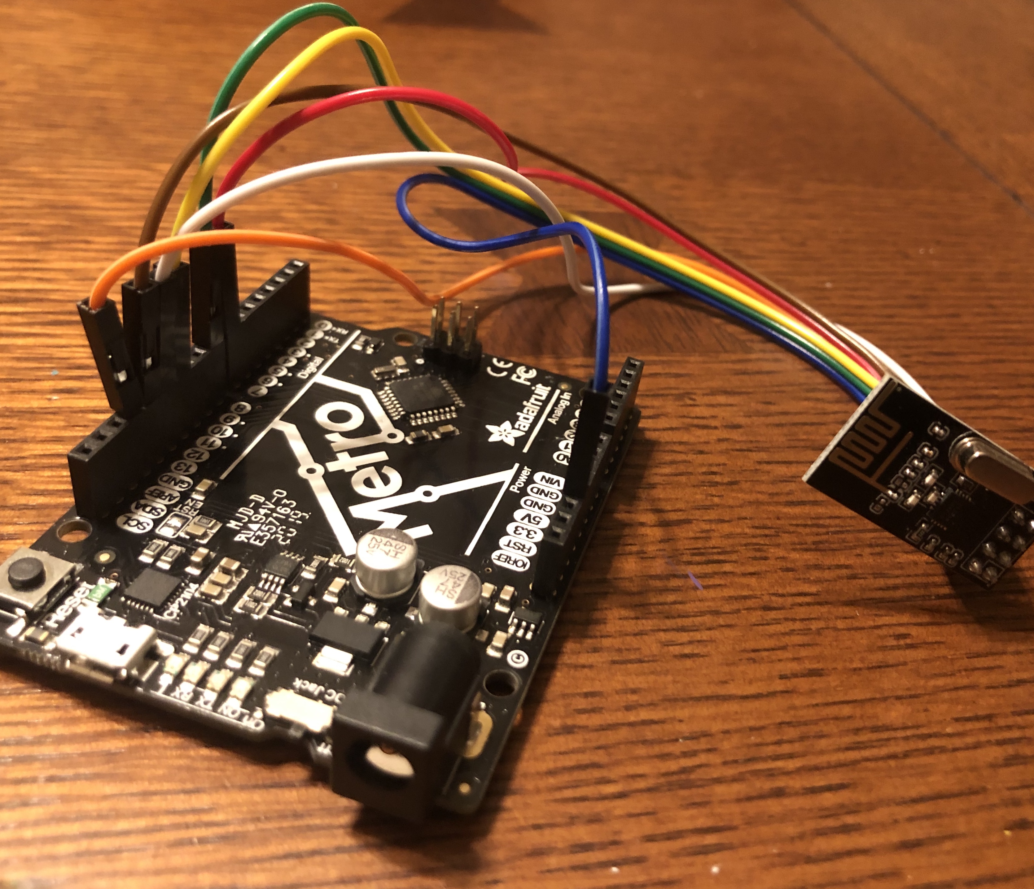
For this week, we had to establish a radio connection between two microcontrollers. I thought about smart lightbulbs that turn on when sound activated. I thought this project would be fairly straightforward, but it proved to be quite difficult when actually getting into it. I faced many problems with the D11 board, which I’m still unable to fully figure out. So instead of using that board, I used my trusty Arduino Metro, which I had managed to save before the chaos of the pandemic.
It took a while to figure out how to connect everything and an even longer time to figure out how to establish a radio connection, but I eventually figured it out! Attached to the left is a demo video, where I use my hand against the table to create a clapping sound which activates the build in LED on the Metro. I’ve attached my code below.
Sender Code
#include <SPI.h>
#include "RF24.h"

/* Hardware coaanfiguration: Set up nRF24L01 radio on SPI bus plus CE and CS */
RF24 radio(32,14);      //CE and CS pins.  This is the change needed when you change to another board.

byte addresses[][6] = {"1Node","2Node"};
byte data = 0;

int soundSensor = 2;

void setup() {
 Serial.begin(1200);
 Serial.println("RF24example:  Simple tx");

 pinMode(soundSensor,INPUT);

  radio.begin();

 // Set the PA Level low to prevent power supply related issues since this is a
 // getting_started sketch, and the likelihood of close proximity of the devices. RF24_PA_MAX is default.
  radio.setPALevel(RF24_PA_LOW);

  // Open a writing and reading pipe on each radio, with opposite addresses

  radio.openWritingPipe(addresses[0]);
  radio.openReadingPipe(1,addresses[1]);

}


void loop() {

int soundvolume = analogRead(A2);

if (soundvolume > 200) {
    Serial.println("Now sending");


    if (!radio.write( &data, 1 )){
    Serial.println(F("failed"));
    }

  data = (analogRead(A2));   //default is 12 bits for ESP32 ADC, so divide by 16 to map to one byte.
    //data++;
  Serial.print("Sent ");
  Serial.println(data);

  delay(100);
}


} // loop end/*
Receiver Code
/*
* Simple sketch for nRF24L01+ radios  Receive side.
*
* Updated: Dec 2014 by TMRh20. Simplified Mar 2019 RMH.
*/

#include <SPI.h>
#include "RF24.h"

/* Hardware configuration: Set up nRF24L01 radio on SPI bus plus pins 7 & 8 */
RF24 radio(8,7);


byte addresses[][6] = {"1Node","2Node"};
int angle;

void setup() {

  Serial.begin(1200);
  Serial.println(F("RF24example:  simple receive"));

  pinMode(LED_BUILTIN, OUTPUT);

  radio.begin();

  // Set the PA Level low to prevent power supply related issues since this is a
 // getting_started sketch, and the likelihood of close proximity of the devices. RF24_PA_MAX is default.
  radio.setPALevel(RF24_PA_LOW);


    radio.openWritingPipe(addresses[1]);
    radio.openReadingPipe(1,addresses[0]);


  // Start the radio listening for data
  radio.startListening();
}

void loop() {

    byte rec_data;

    if( radio.available()){
      while (radio.available()) {
        radio.read( &rec_data, 1 );             // Get the payload
        if ( rec_data > 1) {
          Serial.println(rec_data);
          digitalWrite(LED_BUILTIN, HIGH);   // turn the LED on (HIGH is the voltage level)
          delay(2000);
          digitalWrite(LED_BUILTIN, LOW);   // turn the LED on (HIGH is the voltage level)
        }

      }
     };

} // Loop